Reading the RadioReference Database

One of the best sources for scanner information available is the RadioReference.com database. This is a huge listing of frequencies used thruout the USA and Canada for all types of two-way radio operations.

If you do your own scanner programming then the RRDB is invaluable for information. It is usually more accurate than the agencies themselves have! Even if you only use a database scanner (like a HomePatrol or TRX) then it helps to understand the database so you will have a better idea of what you are listening to. Remember: The data in your scanner came from RadioReference in the first place.

To read the RadioReference database and understand how it works you need to understand how it works. Without understanding how it is laid out it can be daunting, there is a whole lot of information at your fingertips.

To understand it you need to know a couple things. There are two main types of data available, trunked and conventional.

First we will look at a conventional frequency listing. Then we will look at trunking information. (Conventional means that it is not trunked.)

Here is the frequency page for Lee County Florida. It shows several fields:

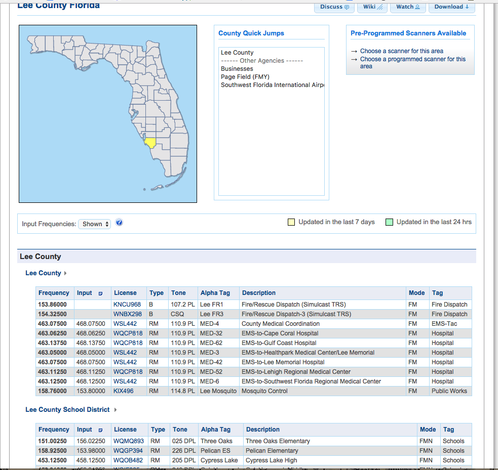
  • Frequency       (Actual frequency used or the repeater output)
  • Input               (Repeater inputs)
  • License            FCC Callsign, click on this to see what frequencies and other info is available for it.
  • Type               Base, Repeater, Mobile only etc.
  • Tone                Could be PL, DPL or NAC 9for P25) etc.
  • Alpha Tag       A short tag used on some scanners, akin to channel numbers etc.
  • Description     A longer description of the channel and its use.
  • Mode              FM, AM, Digital etc.
  • Tag                  The classification that the channel falls under.

If you hover over the column title it will tell you what the codes mean.

Since so many areas use trunking systems these days one might miss a lot of the info needed to monitor the area. Look at the bottom of the county’s page to see a list of trunking systems active in the county. If you see one that appears to be used there click on it to see the data. The first part you will see it the basic info:

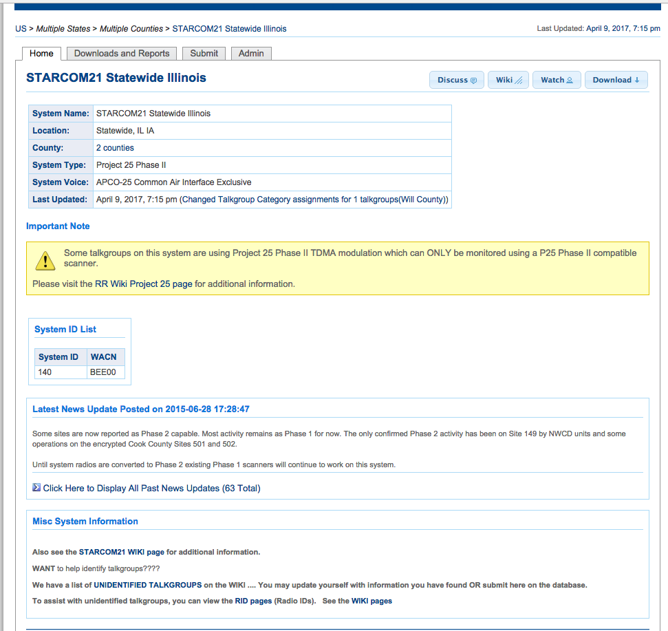
At the top you will see an info box with the system name, location, type and other info. Below that you will see the System ID’s (some scanners will show the System ID to identify it) and other info.

If you scroll down the page next you will see the trunked system Sites. Sites is where you will find the actual frequencies used by the system. Some systems only have 1 or 2 Sites, others (like the one shown) have dozens.

This is a portion of the Site List for the huge Illinois StarCom21 system that has many sites all over the state. There are several columns:

  • RFSS is the Zone number (RF Subsystem), then the Site Number within the Zone. Sometimes Sties are shown in other contexts as X-YYY (1-012 meaning Zone 1, Site 12) or just XYY (112).
  • Next is the Site Name, usually the city or location the site is located in. The county the site is in follows.
  • Last are the frequencies used at that Site. Some freqs will be shown in red, these are known to be “Primary” control channels (mostly for P25 systems). Other freqs will be in blue, these are known to be “Alternate” control channels. The rest are shown in black, these are not know to be used as control channels but are used for voice. Unless you know for sure otherwise, it is usually best to include all channels of the Site in your scanner.

The last part of the Trunked system information is the Talkgroup List. These are the virtual channels used to allow the correct people to communicate within the system.

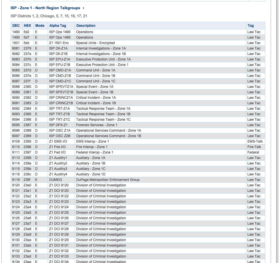
The columns here are:

  • DEC (Decimal)           The most common way to identify a talkgroup in scanners.
  • HEX (Hexidecimal)     Another way to view Talkgroups, used mostly by the fleet radios.
  • Mode                          Tells you if it is Digital (D), Analog (A), Encrypted (E) or TDMA (T).
  • Alpha Tag                   The short channel name
  • Description                 More inclusive description of the channel and its use
  • Tag                              The classification (Service Type) for that talkgroup.

By understanding the way the data is laid out you can apply this to your programming and understanding of the systems you listen to.

Trunking System Types Glossary

Earlier we discussed the differences between Type 1 & 2 and Phase 1 & 2 trunking systems. This week we will discuss some other formats of trunking. I choose to use the easier to understand mnemonics of 1 and 2 rather than the more correct I and II for some of these systems. These mnemonics are often interchanged.

“Motorola” trunking systems include Type 1, Type 2 and Type 2i systems. The original Type 1 systems used a 3600 baud control data signal and a Fleets/Subfleet programming style. In time it was found to be too limiting, it restricted the number of subfleets and radios that could be accommodated within the Fleets. Motorola developed what was called Type 2 trunking that used a similar 3600 baud control data signal but removed the restrictions about Fleets and Subflleets and removed many of the limits on radios. Type 2 systems could have more than 65,000 individual radio ID’s and thousands of Talkgroups.

Some Type 1 systems were upgraded, either to Type 2 or to a hybrid system that allowed both Type 1 and Type 2 radios, this was commonly referred to as Type 2i. A later version of Type 2 trunking, called APCO P16, used the same Type 2 control data but allowed either analog or digital modulation.

APCO P25, as we discussed last week, is an all-digital format sold by several manufacturers, including Motorola, Harris and others. The format was developed by and for APCO and is licensed from them. The system was designed to be interoperable between the several vendors but often they add features that only they can provide so as to rope in customers to continue buying their radios instead of radios from other companies. One way to tell a Motorola designed system apart is by the control channels. On Motorola systems the Control Channel rarely changes and there are only 2 to 4 channels that they would rotate to if one becomes unavailable. Harris designed systems can use any of the channels for control data and some of these rotate the control data regularly.

P25 voice is also commonly used on conventional (non-trunked) channels as well.

There are two main types of P-25; Phase 1 and Phase 2 (or Phase I and II). Phase 1 allows a single conversation on a voice channel while Phase 2, a form of TDMA, allows 2 on each channel, effectively doubling the capacity of the system.

Most scanners these days only require the current Control Data channel for many of the P25 and Motorola trunking systems to track them.

EDACS is a trunking system originally sold by General Electric as a competitor with Motorola Type 1 and later Type 2 systems. This comes in 2 different types, the 9600 Baud control data commonly used on 800 MHz. systems and 4800 baud control data mostly used on UHF and 900 MHz. EDACS systems can use either analog voice or digital voice, called ProVoice. While any trunking scanner can handle analog EDACS systems only certain Uniden scanners (BCD325P2, BCD996P2, BCD436HP and BCD536HP) scanners can monitor ProVoice operations and these require the ProVoice paid upgrade.

EDACS is commonly used for public safety and less often in business applications. It shares many features with the Motorola trunking formats but is not compatible with it. It can be used as Single Site, Simulcast or Networked or some combination of these.

After several years GE sold the EDACS product line and it bounced around to several companies before landing at Harris Communications. Since EDACS is no longer sold or supported by Harris many of the systems have been shut down or converted to other formats. At some point EDACS systems will all be shut down as parts become unavailable for repairs.

To program an EDACS system into a scanner one needs to put the channels in their proper assigned slots. This is called the “LCN” (Logical Channel Number). This is because the radio only sends the channel number, it is up to the scanner or other radio to match this with the actual frequency.

LTR (Logic Trunked Radio) is a popular format for business users and occasionally used for public safety. This format does not use a dedicated control channel like Motorola, EDACS or P25 systems do. Instead data is sent piggybacked onto the regular traffic on the channel advising specific radios to go to a channel for a message. While this allows all channels to be used for voice messages it is not as robust as other systems so is not often used for police and fire use.

One can tell is an LTR system is in us, there is a characteristic repeater key-up on most channels. This is sending data to radios assigned to that channel as it’s “Home Channel”. Most trunking scanners can handle LTR systems, the trick is determining the LCN slots properly.

DMR/TRBO/NXDN systems can be either conventional or trunked. Some systems can be trunked with a single channel, using sub-audible codes to separate the groups. These systems use TDMA for voice traffic so multiple conversations can be carried on one channel.

While used mostly for business activities these systems occasionally are used for public safety, especially in the SE states.

MotoTRBO is a brand name used by Motorola for it’s DRM offering. While there are slight differences a DMR scanner works fine for unencrypted TRBO systems.
DMR is available on certain Uniden and Whistler scanners.

NXDN trunking is very similar to DMR but just different enough to require a different mode. As of this writing (Spring 2017) NXDN was only available on the TRX-1 and TRX-2 scanners by Whistler.

Type 1, Type 2, Phase 1, Phase 2, what’s the difference?

There is often confusion between different types of trunked systems. One of the most confusing things is the names of some systems. We get calls and letters all the time asking about Phase 2 and Type 2 systems and whether a particular scanner will work on them. They are different and the difference will determine if your scanner will work with it.

TYPE 2 (more accurately but less often written as TYPE II) systems are older Motorola trunking systems that use 3600 baud control data channels. These are commonly referred to as just “Motorola” systems when programming scanners. These were an evolution from the original Type 1 and Type 2i systems. The difference between Type 1, 2i and 2 systems is the way talkgroups are developed. Type 1 systems use a Fleet/Subfleet system that resulted in limited flexibility to assign talkgroups. Most of these systems have been shut down or updated and very few remain in use. Type 2 systems had a different method of assigning talkgroups and allowed greater flexibility. Some systems were called Type 2i, and were a hybrid between Type 1 and Type 2 systems.

Newer Type 2 systems, referred to as APCO P16 systems, allowed either digital, analog or both forms of modulation. There are still many of these systems in use all over the country.

PHASE 1 and PHASE 2 (more accurately referred to as Phase I and Phase II) systems are totally different than Type 1 or Type 2 systems. Phase 1 and 2 systems are forms of APCO P-25 digital systems that use 9600 baud control data channels and all digital modulation. Phase I systems have a single voice path per frequency while Phase II allows 2 voice paths per frequency, effectively doubling the amount of traffic a set number of channels can handle.

It gets even more confusing when programming some radios. Some scanner program the Type 2 and Phase 1 or 2 systems with the same system type, others have different selections. On the user end, most Motorola P25 (Phase 1 or 2) radios are also capable of being used on the older Type 2 systems.

Next week we will look at some of the other trunking systems like EDACS, LTR and TRBO.

Scanner Tip: Everything you need to know about trunking but were afraid to ask

In the old days of scanning things were pretty simple, you put in the local police frequency to listen to the police. In many parts of the country however, this no longer works. Most cities, many counties and even entire states use Trunking Systems. What are trunking systems and how do they work?

The best way to explain how a trunking system works is the analogy of a set of bank teller lines. The bank has 5 tellers, you can line up at any of the 5 lines and hope your line goes faster than the others. Then you get stuck behind the lady that wants to have her penny jar counted by hand…

These days however, banks have a single queue and you go to the next available teller when you reach the head of the line. This is exactly how a trunked radio system works: All users are in one queue and get assigned the next available channel. Instead of having a separate frequency for the FD, one for the PD and another for the ambulance, they just go to the next channel that isn’t being used.

All this is controlled by a computer system called, appropriately enough, a “Controller”. The Controller watches the system and when a radio requests to talk it assigns that radio and any other radio in its group to a channel. All this happens in a fraction of a second.

Radios have all the frequencies used by the system programmed into them and the system is broken down into various virtual channels, called “Talkgroups”. Talkgroups are assigned to various uses like channels would have been before. For example, Mayberry PD might be assigned Talkgroup 101 for Dispatch, 102 for Car-Car and 103 for Detectives. Mayberry FD might be assigned Talkgroup 123 for Dispatch, 124 for Fireground and 125 for Tactical. If Mt. Pilot is sharing the system they might be assigned Talkgroup 287 for Police Dispatch and so on.

There are several types of trunking systems but they all work in much the same way. There are differences in the way they get programmed into scanners as well. The main types of trunked systems in use by Public Safety agencies in the USA include Motorola, EDACS, LTR, APCO25 Phase 1 and APCO25 Phase 2.

For scanner listeners these trunked systems add a layer of complexity to the programming. Depending on the type of scanner and the type of trunked system the method used to program differs. For newer Unidens you program in a “System” to identify the type of trunking, then “Sites” to put in the frequencies used and lastly “Groups” for the talkgroup listing. Whistler, GRE and Radio Shack scanners with Object Oriented programming work differently. On LTR and EDACS systems you have to identify the proper “LCN” channel numbers, these are usually well documented at www.radioreference.com. Motorola and APCO25 systems do not need the frequencies in any particular order.

HomePatrol and other scanners with the Database feature will have these Trunked System parameters already programmed so you can just select the Service and location to listen to them. They do all the heavy lifting for you.

Keep an eye on the ScannerMaster Blog for our explanation of Digital operations!